Testing & Inspection
Advanced & Conventional NDT Services
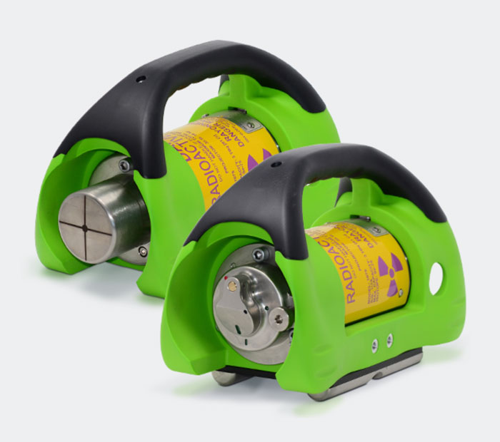
SCAR - Small Controlled Area Radiography using SENTINEL 1075 SCAR Pro
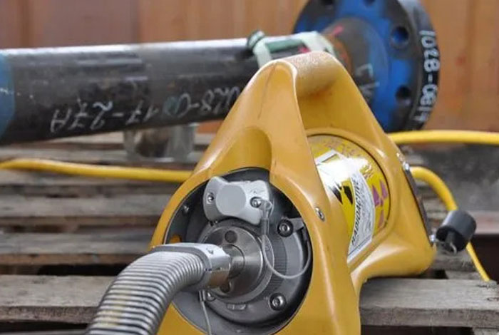
The SCAR Radiography technique utilizing the SENTINEL 1075 SCARPro eliminates the need for shooting windows or impacting other trades. The SENTINEL 1075 SCARPro enables continuous 24/7 gamma radiography inspections maximizing inspection productivity and accelerating your turnaround.
Perform Small Controlled Area Radiography (SCAR) radiographic inspections in close proximity to other trades, nucleonic process control equipment, and critical safety systems, such as visual flame detectors, to minimize the impact of RT on continuing operations or outage schedules.
Utilizing FlexShield radiation blankets, guide tube shields, and scatter shields with proper technique, we can achieve exclusion zones as small as 3 to 6 feet (1 to 2 meters) for demanding applications or 10 to 15 feet (3 to 5 meters) for typical applications required by clients to realize the SCAR value.
Phased Array Ultrasonic Testing using Olympus OmniScan MX2
Pressure Vessel Weld Inspection
A complete inspection of pressure vessel welds can be performed in a single scan using an OmniScan PA and manual scanner such as the HSMT series or a motorized scanner like the WeldROVER. By combining TOFD and PA in a single inspection pass, a significant reduction in inspection time can be achieved as compared with conventional raster scanning or radiography. Furthermore, inspection results are available immediately, enabling you to detect problems with welding equipment and fix them right away.
Composite Inspection
Parts made of laminate composite materials pose an inspection challenge due to their various shapes and thicknesses.Olympus offers complete solutions for the inspection of carbon-fiber-reinforced polymer structures. These solutions are based on the OmniScan flaw detector, the GLIDER™ scanner, and dedicated probes and wedges designed for CFRP flat panel and radius inspection.
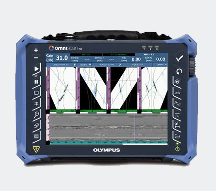
Weld Inspection of Small-Diameter Pipes:
When coupled with the COBRA manual scanner, the OmniScan flaw detector is capable of inspecting pipes ranging from 0.84 in. OD to 4.5 in. OD. With its very slim design, this manual scanner is able to inspect pipes in areas with limited access. Adjacent obstructions such as piping, supports, and structures can be as close as 12 mm (0.5 in.).
Manual and Semiautomated Corrosion Mapping:
The OmniScan PA system with the HydroFORM scanner is designed to offer the best inspection solution for detecting wall-thickness reductions resulting from corrosion, abrasion, and erosion. In addition, this system detects mid-wall damage, such as hydrogen-induced blistering and manufacturing-induced delamination, and clearly differentiates such anomalies from loss-of-wall-thickness. For this application, phased array ultrasound technology offers superior inspection speed, data point density, and detection.

MPT (Magnetic Particle Testing)
This method is used for the detection of surface and near-surface flaws in ferromagnetic materials and is primarily used for crack detection. The specimen is magnetized either locally or overall, and if the material is sound the magnetic flux is predominantly inside the material. If, however, there is a surface-breaking flaw, the magnetic field is distorted, causing local magnetic flux leakage around the flaw. This leakage flux is displayed by covering the surface with very fine iron particles applied either dry or suspended in a liquid. The particles accumulate at the regions of flux leakage, producing a build-up which can be seen visually even when the crack opening is very narrow. Thus, a crack is indicated as a line of iron powder particles on the surface.
The method is applicable to all metals which can be strongly magnetized – ferritic steels and irons, but not generally austenitic steels.
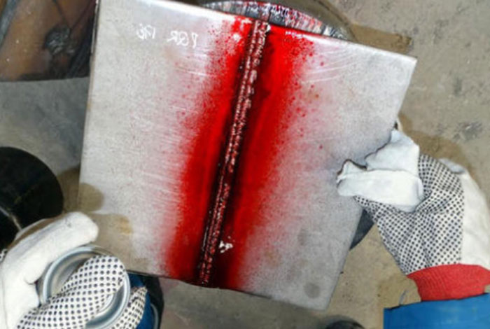
LPT (Liquid Penetrant Testing)
Liquid penetrant testing (LPT Test) is one of the most widely used non-destructive testing methods. LPT test is based on capillarity or capillary attraction, where a liquid is able to flow into narrow spaces without the assistance of – or even in opposition to – external forces such as gravity. The materials processes and procedures used in liquid penetrant testing are designed to make the results of this capillary action visible and capable of interpretation. Liquid penetrant testing is an effective means of locating and determining the severity of surface discontinuities in materials, including those that are not visible to the naked eye.
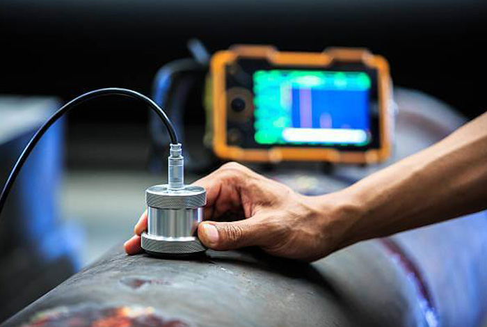
UT (Ultrasonic Testing)
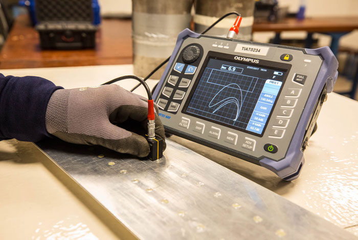
Ultrasonic testing (UT) comprises a range of non-destructive testing (NDT) techniques that send ultrasonic waves through an object or material. These high frequency sound waves are transmitted into materials to characterize the material or for flaw detecting. Most UT inspection applications use short pulse waves with frequencies ranging from 0.1-15 MHz, although frequencies up to 50 MHz can be used. One common application for this test method is ultrasonic thickness measurement, which is used to ascertain the thickness of an object such as when assessing pipework corrosion.
UTG (Ultrasonic Thickness Gauging)
Ultrasonic thickness gauges have been used for many decades to measure the thickness of a wide variety of products across various industries. This includes inspectors testing critical parts, such as checking pipes and tanks for in-service corrosion. In most cases, an ultrasonic thickness gauge is used to determine the thickness of a material when the inspector only has access to one side of the part, such as a pipe or tube, or when simple mechanical measurement is impossible or impractical due to the part’s size or access limitations. The ability to quickly and easily measure thickness from one side without the need to cut parts is one of the major advantages of this technology.

VT (Visual Testing)
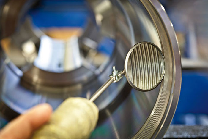
Visual Testing (VT) is based on the inspection for flaws that are visible to the naked eye and is the most commonly used NDT method across all industries. It allows for a feasible and fast control of quality at every step of the fabrication or maintenance process.
Visual Testing (VT) is used to detect visible flaws such as deformation, welding defects and corrosion. Many tools can be used during the inspection such as a ruler, gauges, cameras, etc.
Drone Inspection
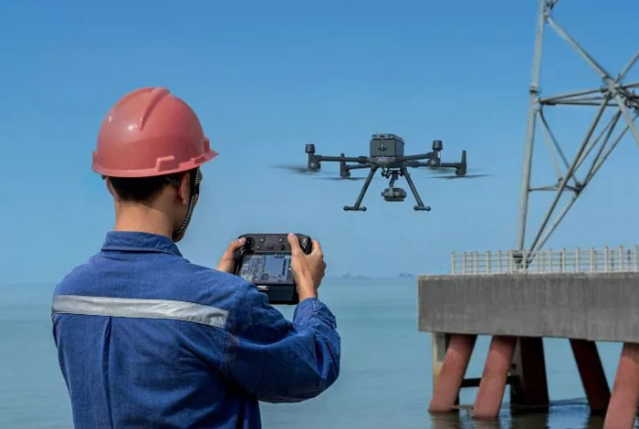
During the drone-based visual inspection, a collision tolerant drone can be deployed in confined spaces or inaccessible areas. A team composed of an inspector and a drone pilot conduct the inspection from a safe location enabled by a powerful lighting system, a 4k video camera and a thermal camera which is installed on the drone.
PMI (Positive Material Identification (XRF & OES))
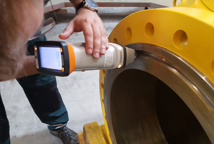
Positive material identification (PMI) is an essential non-destructive testing (NDT) method utilized to verify that supplied materials conform to the proper standards and specifications. Specifically, PMI is used to confirm that the chemical composition of the metallic parts has the correct percentage of key elements, this ensures that material properties such as corrosion resistance meets the requirements.
The PMI is utilized for quality control and safety compliance and is an integral part of both production and asset integrity management across many industries including oil and gas, power generation, chemical, pharmaceutical, nuclear, aerospace, and metal fabrication.
FT(Ferrite Testing)
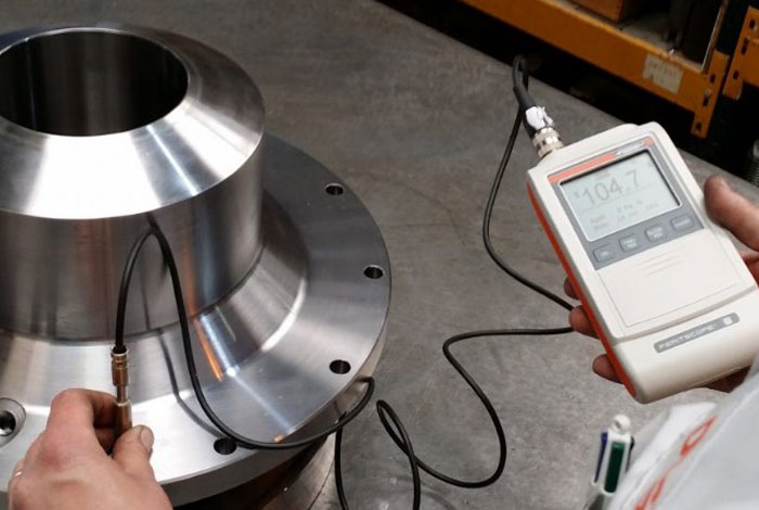
What is ferrite testing? Ferrite testing is an accurate, very quick and inexpensive method of determining the percentage of ferrite in austenitic and duplex stainless steel. Material testing technicians will carry out this type of test to make sure that the stainless steel being used in or for various processes is properly tough, is resistant to corrosion and will not crack.
Different types of stainless steel require different percentages of ferrite, depending on the job they need to perform. Ferrite testing is used within a range of different industries. These include chemical, mining, manufacturing, oil and gas, paper and power generating. Ferrite testing verifies whether heat treatment applied to the material has reached the required performance balance. It also shows whether there are any damaging third phases in materials, which could later inhibit the performance of stainless steels. It will also highlight any weld strength deficiencies.

HT(Hardness Testing)
Hardness testing measures a material’s resistance to permanent deformation at its surface, by pressing a harder material into it. It is used in a number of industries for material comparison and selection, as well as quality control of a manufacturing or hardening process. A specifically manufactured indenter, with chosen dimensions, is used to press into the material being tested, with a prescribed force. The pressing time is also important in the hardness test.
Hardness is not a fundamental physical property of a material, but rather a measured characteristic. It can however provide some valuable information about the strength and durability of a material, depending on the application it is intended for.
ET(Eddy Current)
Eddy current testing is a non-destructive test method that can be performed on conductive materials. A test coil that is energized with alternating current is placed close to the test surface. This generates an alternating magnetic field that produces eddy currents in the test piece. Variations in eddy current flow produce a measurable change in the test coil. These changes are shown on a screen and interpreted to identify defects. The presence or absence of flaws in the test specimen can be determined by monitoring changes in the impedance of the eddy current test coil. Changes in coil impedance are displayed as voltage changes in terms of signal amplitude and signal phase. These variations in phase angle and/or signal amplitude are correlated to flaw conditions, such as percent wall loss and volumetric wall loss.
The eddy current inspection method can be used to detect degradation as well as determine the test part’s conductivity, and the thickness of coatings applied to conductive materials.
RT (Radiography Testing)
Radiographic Testing (RT) is a non-destructive testing (NDT) method which uses either x-rays or gamma rays to examine the internal structure of manufactured components identifying any flaws or defects.
In Radiography Testing the test-part is placed between the radiation source and film (or detector). The material density and thickness differences of the test-part will attenuate (i.e. reduce) the penetrating radiation through interaction processes involving scattering and/or absorption. The differences in absorption are then recorded on film(s) or through an electronic means. In industrial radiography there are several imaging methods available, techniques to display the final image, i.e. Film Radiography, Real Time Radiography (RTR), Computed Tomography (CT), Digital Radiography (DR), and Computed Radiography (CR).
There are two different radioactive sources available for industrial use; X-ray and Gamma-ray. These radiation sources use higher energy level, i.e. shorter wavelength, versions of the electromagnetic waves. Because of the radioactivity involved in radiography testing, it is of paramount importance to ensure that the Local Rules is strictly adhered during operation.
Vacuum Box Testing
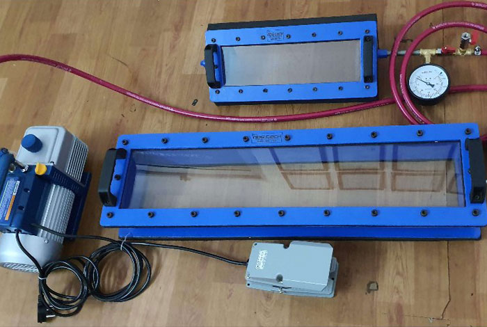
Vacuum box testing is a non-destructive examination used when trying to locate weld seam leaks. A vacuum box and a compressor create a high- or low-pressure vacuum while a detergent solution is applied to the test area. The detergent bubbles, making leaks visible within the created pressure envelope. IRISNDT utilizes systems compliant with ASTM E515. All inspections are conducted within the parameters of ASME Section V Article 10, Appendix II or to client specifications.
We Applies Vacuum Box Testing To Inspect
- Lap welds, butt welds, and shell to annular welds
- Piping systems and pressure vessels
- Tank bottoms
- ERW seamed pipe in pipelines
- Objects on which a pressure differential can be created across the area to be examined

Filim Digitization
At OMNITECH, we are continually introducing value-added services to our ndt services. One such service, is our digitizing capability. We have constructed a special digitizing/film-reading room to accommodate the digital processing of large quantities of radiography film.
Scannix 2905 is an industrial X-ray film digitizer specifically designed to offer the best quality images for the NDT market. Not an additional operation but a true improvement.
The Scannix 2905 is driven by our Acquisition software and is delivered with the scanner as a standard. As a digital image, a radiography can also be processed with our Image Processing Software IPS012 allowing details that were hidden to appear, thanks to different filters and the contrast settings but also a lot of different tools and add-on like SRb, SNR, etc. Acquisition can also be linked to IPS012 allowing an automatic transfer of the image to start processing the radiography. Scanning radiographies will also improve and fasten communications as digitized version can easily be sent by email to a customer or an expert. Not only because it is environment friendly but also because it is an inexpensive operation to perform, High definition scanning of your films is the key solution to improve your service quality and extend your inspection capabilities.
Alternating Current Field Measurment
Alternating Current Field Measurement (ACFM) is an advanced Non-Destructive Testing (NDT) technique designed to detect and size surface-breaking cracks in metals through coatings with an excellent surface tolerance compared to PEC.
For 30 years, ACFM electromagnetic inspection technology has been the method of choice for detecting and sizing subsea surface-breaking cracks. Recognized and approved by many certification bodies, including DNV, ABS and Lloyds, the technique has been used successfully to supersede traditional non-computerized and more user-dependent methods, such as magnetic particle inspection (MPI). As today’s industry is looking to scale the use of auditable NDT methods to all their assets, faster, more flexible, remotely deployed inspections and better reporting capabilities are required.
TSC Subsea’s ACFM technology was initially designed to assist divers in identifying and sizing fatigue cracking in jacket structures. Consequently, it is no surprise that this NDT technique has evolved into a standard for detecting and defect sizing of subsea cracks.
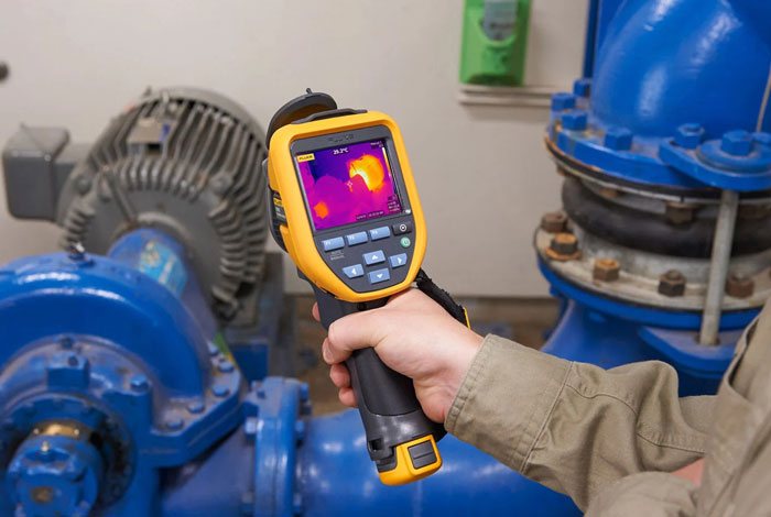
Thermography Testing
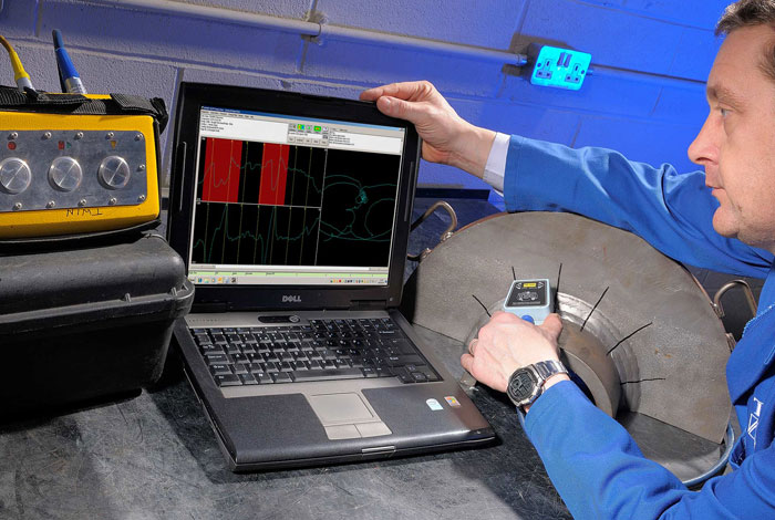
Thermographic testing uses infrared detection and mapping to identify temperature changes in operations, heat flows through equipment, and temperature comparisons for various components and areas. Infrared thermographic testing detects thermal waves that are invisible to the naked eye. It can aid in predictive maintenance by using data about temperature fluctuations to identify potential maintenance issues that might lead to equipment failure and shutdown.

